You don’t hear much about Process Damping, but it is an important phenomenon in milling. We have discussed the waviness caused by the flexible milling tool’s vibration frequency and the use of a Stability Lobe Diagram (SLD) to select the right speed to match that frequency. But, there is a speed zone on the SLD from zero to a certain RPM where the cut is stable, at full width and depth of cut, not from matching vibration, but from actually eliminating it.
This is called the Process Damped (PD) Region and here is how it works:
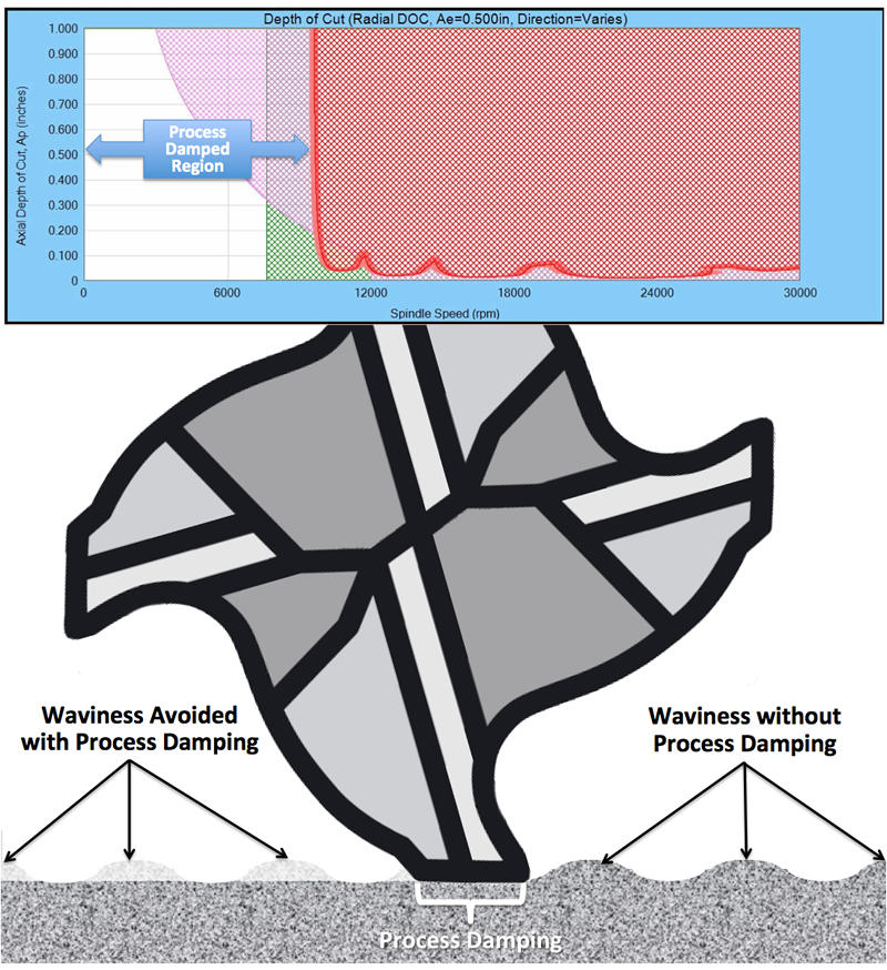
The geometry of the milling tool, specifically the relief behind the cutting edge acts as a vibration damper. As the tooth goes through the cutting zone the relief area rubs the surface and absorbs the energy that would otherwise deflect the tool. Sometimes the PD range is enough to allow for very high metal removal rates, especially in tougher to machine materials.
Other elements of the tool can increase PD. This includes honing of the cutting edge and non-proportional spacing of the teeth. In the case of the latter, the second closely following tooth acts as a damper to a primary tooth that is in the cut longer. The PD range always starts at 0 RPM, but its max speed is determined by the flexibility of the tool (tap-test) and its PD Wavelength.
If you manufacture or use endmills with high process damping you can measure and quantify the effect using the SpeedCast tap testing kit, software and Harmonizer: https://speedcasttraining.s3.us-west-2.amazonaws.com/New+Tool+and+Material+Characterization+-+Presenter+output/presentation.html
Here is an article explaining process damping: https://www.mmsonline.com/articles/understanding-process-damping-in-milling-operations